1600i Hydraulic Tappets Information
Common Hydraulic Tappet Problems:-
A common problem with the 1600i
engine is rattling hydraulic tappets, especially after the car has not been
driven for a few days. This could be
caused by any of the following:-
-
Engine stood idle for a few days
(about 2 days or longer).
-
Incorrect Oil Type/Grade. Use 15W40
mineral engine oil only !!
-
Oil level too low !! Top up the oil level, but never overfill it !!
-
Sludge within the engine oil.
-
Air present within the hydraulic
tappets themselves (e.g. air inside its piston)
The following sections will attempt
to explain how to stop the hydraulic tappets from rattling.
Drive the Car!:-
The first simple solution to this
problem is to simply drive the car carefully for about 15 minutes. The engine should have stopped rattling by
then.
Flush Out the Sludge Within the
Engine:-
If the engine has not stopped
rattling after it has warmed up (after about 15 minutes) then the engine may
have sludge within its own oil.
To remove the sludge, do the
following:-
-
At 200 miles (300 km) before the
next service is due, add some liquid molybdenum disulphide (e.g. Liquid Moly)
to the engine’s own oil.
-
Drive the car normally for the next
200 miles (300 km).
-
Flush out the engine with engine
flush and change the oil.
Increase the Oil Flow:-
The oil flow-rate can be increased
by turning out the very large cheese-headed bolts on the bottom of the
crankcase. These are located on the
left hand side of the crankcase. The
front one is next to the gearbox and the rear one is next to the oil filter.
Another possible solution is to
replace the oil pressure relief valves (this problem is rare).
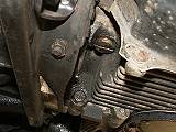
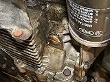
Front oil pressure relief valve Rear oil pressure relief valve
Caution! Make sure that
you do not increase the oil flow-rate by too much otherwise oil may
leak through the engine’s gaskets !!
Remove the Air from the
Hydraulic Tappets (last resort !):-
If the above did not work, then there may be air present
within the hydraulic tappets. This will
require the engine to be removed from the car and its crankcase split. This is not for the faint-hearted !!
To check to see if there is air present within the hydraulic
tappets, do the following:-
-
Unclip the rocker covers and remove them
-
Push down on each of the rocker arms where they connect to
the push rods within the cylinder heads.
The rocker arms should not move under heavy thumb pressure. If any of them do then those tappets will
have air present within them.
Use heavy thumb pressure on these parts of the rocker arms.
![]()
If air is present within any of the tappets, then do the
following:-
-
Remove the engine from the car (see the Engine Removal and
Re-Installation section for further information).
-
Remove the distributor.
(Make sure that you mark up both the distributor and the crankcase with
a marker pen. This will help you to
re-install the distributor back into it’s correct position).
-
Remove the distributor gear. Be careful that you do not damage it during the process !
-
Remove the crankshaft pulley wheel.
- Remove the clutch and flywheel. The flywheel its self will be very
tight. Use a
very large torque wrench, a long bar and
a flywheel locking tool to undo the
flywheel nut. Be careful that you don’t hurt yourself !!
-
Split the crankcase.
- Remove the camshaft from the
crankcase. The hydraulic tappets should
now be
accessible.
To remove air from the tappets, do the following:-
-
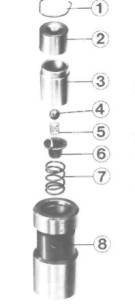
Pry off the circlup (1) from the top of the hydraulic
tappet’s piston.
- Remove the pushrod end of the piston (2),
the piston it’s self (3) and its spring,
etc . (items 4 to 7).
-
Now fill up the tappet with engine oil via the tappet’s
lateral drilling (8) whilst the tappet is upright.
-
Re-assemble the hydraulic tappet, which is done by doing the
following:-
- Use an old pushrod and saw one end of it
off.
- Now put the hydraulic tappet and the
sawn-off pushrod into a vice.
When you are re-assembling the tappet,
make sure that the ball (4) is located
in the cup (6) is located correctly as
shown below. You may need a piece of
wire or a very small screwdriver to do
this.
-
Slowly do up the vice to push the hydraulic tappet back
together.
Replace the circlip once the hydraulic
tappet has been squeezed up together.
-
The hydraulic tappet should now be ready for use and can be
put back into the
engine.
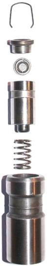
Exploded view of a hydraulic
tappet:- 1. Circlip 2. Pushrod End 3. Piston 4. Ball 5.
Small
Spring 6.
Cup Washer 7.
Large
Spring 8. Tappet Housing’s (Laterel) Oil Drilling
If the hydraulic tappet is badly worn out or damaged then it
must be replaced !!
Here’s what a real 1600I hydraulic tappet looks like:-
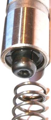
Circlip Pushrod end Bearing ? Piston Spring Hydralic Tappet Housing
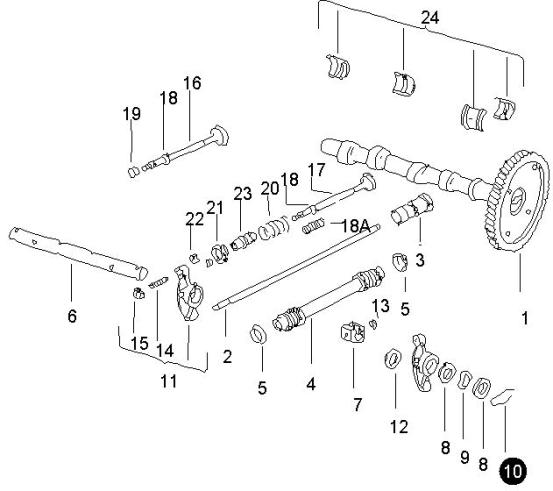
Full exploded
views of a 1600i hydraulic tappet
After all of the hydraulic tappets have had the air removed
from them, then the following should be done:-
-
Re-install the camshaft in the crankcase
-
Re-assemble the crankcase
-
Re-assemble the clutch, flywheel and crankshaft pulley
-
Re-install the engine back into the car
-
The hydraulic tappets should now be left to settle for at least 10 minutes before you do
anything else.
After the hydraulic tappets have been settled, the
adjustment of them must now be checked.
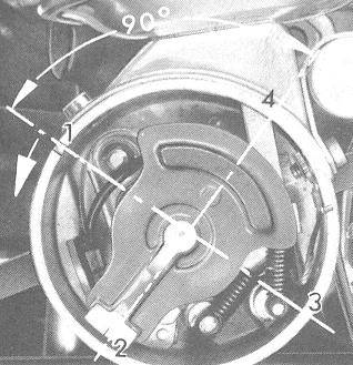
Checking the firing-point of
each cylinder. The rotor arm should
line up with the notch on the distributor when cylinder 1 is at it’s
firing-point. Note the direction of the arrow
! This is the direction that you
should move the engine with a ratchet and socket. Note: This is
not a real 1600i distributor but an old carburettor-based one.
Distributor – Inner View
First of all move the crankshaft until the number 1 cylinder
is at it’s firing-point. A good way of knowing
when it is at it’s firing point is to look at the rotor arm inside the
distributor as shown below:-
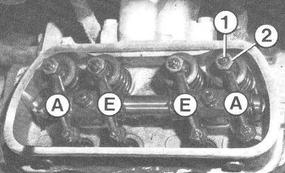
The inlet and exhaust valves for the number 1 cylinder can
now be adjusted. The photo below shows
the layout of the cylinder head:-
Cylinder Head (Inner View) 1 = Adjustment Screw 2 = Locking Nut A = Exhaust Valve (Auslaßventil) E = Inlet Valve (Einlaßventil)

Adjust cyllinder one’s exhaust (A) valve. Slacken the locking nut (2) and turn the adjustment
screw (1) until the screw just touches the rocker arm. Now tighten that screw by a further 1 ½
turns and tighten-up the locking nut.
Make sure that the adjustment screw does not rotate when you tighten-up
the locking nut !!
Repeat the same procedure for number one cylinder’s inlet
(E) valve.
Now rotate the engine until cylinder 2 is at it’s firing
point.
Note: There are no markings on the distributor’s housing for cylinders 2, 3 and
4.
Use a protractor
and a marker pen to mark up the firing points of cylinders 2, 3 and 4.
These
will be at 90° away from each other.
Repeat the same procedure for cylinder 2.
Repeat the same procedure for cylinders 3 and 4.
After the hydraulic tappets have been adjusted, re-install
the rocker arm covers and the engine should not rattle anymore.
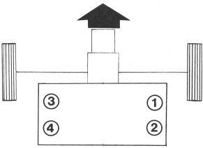
Overall Engine View Diagram:-
Gearbox

Engine

|
Gearbox |
|
Engine |
Engine (Cross-Sectional View):-
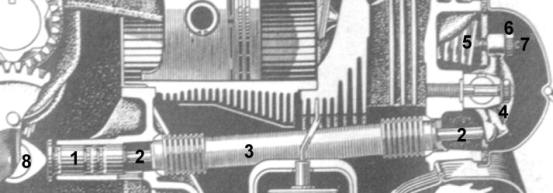
Hydraulic Tappets Items:-
1 = Hydraulic Tappets 5
= Valve Stems
2 = Push Rods 6
= Locking Nuts
3 = Push Rod Tubes 7
= Adjustment Screws
4 = Rocker Arms 8
= Camshaft
Engine Parts List:-
Parts List
Item VAG Part # Description Quantity
Required
3 043 109 309 Hydraulic
tappets 8
2 113 109 301 E Push Rods F > > 11-T-021 008 8
2 043 109 301 Push Rods F 11-T-021 009> > 8
4 113 109 337
A Push Rod Tubes 8
5 113 109 345 A Hydraulic tappet seals 16
This document was translated into english (in my own words
from what I have understood of it) by myself, Phil Ade on Tuesday 14th
March 2006.
This documentation has also been updated on Tuesday 17th
April 2007 by Phil Ade.
The original german documentation is on the 1600i website (www.1600i.de)
in various sections.