© www.1600i.de
created 30.12.2007
Checking and repairing the ECU’s relay:-
One of the most common fault which cause any of the following is usually
down to the relay 30 (the ECU’s relay) being faulty:-
-
Erratic idle speed
-
Engine running badly at no-load
-
Engine stalling for no apparent reason
-
Error 0532 ECU voltage too low
-
Several errors logged by the ECU
Note: The engine could still be running
badly if the ECU relay is faulty and no
errors were logged by
the ECU.
If the ECU relay is suspect, then it should be removed and either
repaired or replaced. A replacement
relay costs about 10-odd Euros or about 10-odd pounds in the UK.
The ECU relay is located in the front boot compartment on the left hand
side of the car (arrowed):-
The relay its self can be removed carefully by pulling it upwards away
from it’s socket whilst holding down relay 80 (the fuel pump relay) at the same
time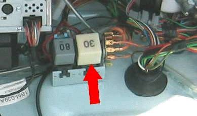
. Make sure that you do not break the relay
sockets !!
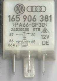
The VAG part number of the ECU relay is 165 906 381, which is shown
below:-
This ECU relay also fits the
following vehicles:- -
Type 2 T4 (Bus T4, etc.) -
Golf Mk 3 and Mk 4 -
Vento -
LT Mk 2 -
Audi A4, A6, 100 (1993) -
Audi 80 and 90 (1992-on) -
Audi Coupe -
Caddy (1996 – 2003) -
Passat Mk2 and Mk3, Santana -
Polo Mk2 -
and several other VWs
To fix the relay its self, you will have to remove the plastic cover
from the relay its self. To remove it
you will need to do the following:-
-
Use two jeweller’s screwdrivers (one on each side of the relay) to
gently prise off the plastic cover outwards from the relay’s base.
-
Now lift up the plastic cover upwards away from the relay’s base.
-
You should now be able to get at the relay’s PCB.
The most common problem with the ECU relay is usually dried solder
joints on the relay’s PCB. These will
cause an intermittant (or non-existant) electrical connection between the
component(s) and the PCB its self.
The photo below shows (in this case) where there are dried joints on the
relay’s PCB, which are indicated by the red arrows:-
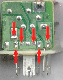
The solder joints shown in the photo above shows that there are several
dried joints on the relay’s PCB. Notice
the difference between the solder joint on the left hand side of the photo and
the rest of them.
Note: The relay its self may have
different dried solder joints compared to the
one in the photo
above.
These solder joints should now be cleaned up and resoldered. Use a soldering iron, solder and a solder
sucker to do this. Once those solder
joints have been redone, the relay’s PCB should now look like the one shown in
the photo below:-
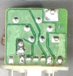
Now compare the two different photos and notice how shiny and complete
the solder joints are. This should now
fix the ECU relay problem.
Now refit the relay back into it’s relay socket, connect up your
diagnostics kit and start the engine.
Now read the fault codes from the ECU and erase them. The engine should then run normally.
This document has been translated (in my own words) by Phil Ade,
Saturday 3rd November 2007.